


Description
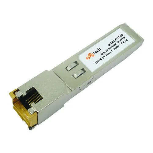
GOXS-C12-02 Copper SFP Transceiver · Up to 1.25Gb/s bi-directional data links Hot-pluggable SFP footprint · Extended case temperature range (0°C to +85°C ) Fully metallic enclosure for low EMI · Low power dissipation (1.05 W typical) Compact RJ-45 connector assembly · Access to physical layer IC via 2-wire serial bus 1000 BASE-T operation in host systems with SERDES interface · 10/100/1000Mbps compliant in host systems with SGMII interface 25 Gigabit Ethernet over Cat 5 cable GOCS-C12-02 Copper Small Form Pluggable (SFP) transceivers is high performance, Cost effective module compliant with the Gigabit Ethernet and 1000- BASE-T standards as specified in IEEE 802. 3-2002 and IEEE 802.3ab, which supporting 1000Mbps data- rate up to 100 meters reach over unshielded twisted-pair category 5 cable. The module supports1000 Mbps full duplex data-links with 5-level Pulse Amplitude Modulation (PAM) signals. All four pairs in the cable are used with symbol rate at 250Mbps on each pair. The module provides standard serial ID information compliant with SFP MSA, which can be accessed with address of A0h via the 2wire serial CMOS EEPROM protocol. The physical IC can also be accessed via 2wire serial bus at address A0h Pin Signal Name Description Plug Seq. Notes 1 VEET Transmitter Ground 1 2 TX FAULT Transmitter Fault Indication 3 Note1 3 TXDISABLE Transmitter Disable 3 Note2 4 MOD_DEF(2) SDA Serial Data Signal 3 Note3 5 MOD_DEF(1) SCL Serial Clock Signal 3 Note3 6 MOD_DEF(0) TTL Low 3 Note3 7 Rate Select Not Connected 3 8 LOS Loss of Signal 3 Note 4 9 VEER Receiver ground 1 10 VEER Receiver ground 1 11 VEER Receiver ground 1 12 RX- Inv. Received Data Out 3 Note 5 13 RX+ Received Data Out 3 Note 5 14 VEER Receiver ground 1 15 VCCR Receiver Power Supply 2 16 VCCT Transmitter Power Supply 2 17 VEET Transmitter Ground 1 18 TX+ Transmit Data In 3 Note 6 19 TX- Inv. Transmit Data In 3 Note 6 20 VEET Transmitter Ground 1 Notes: Plug Seq.: Pin engagement sequence during hot plugging. TX Fault is an open collector output, which should be pulled up with a 4.7k~10kΩ resistor on the host board to a voltage between 2.0V and Vcc+0.3V. Logic 0 indicates normal operation; logic 1 indicates a laser fault of some kind. In the low state, the output will be pulled to less than 0.8V. TX Disable is an input that is used to shut down the transmitter optical output. It is pulled up within the module with a 4.7 ¨C 10 K Its states are: Low (0 to 0.8V): Transmitter on (>0.8, < 2.0V): Undefined High (2.0 to 3.465V): Transmitter Disabled Open: Transmitter Disabled Mod-Def 0,1,2. These are the module definition pins. They should be pulled up with a 4.7K to 10K resistor on the host The pull-up voltage shall be VccT or VccR Mod-Def 0 is grounded by the module to indicate that the module is present Mod-Def 1 is the clock line of two wire serial interface for serial ID Mod-Def 2 is the data line of two wire serial interface for serial ID LOS (Loss of Signal) is an open collector/drain output, which should be pulled up with a 7K to 10K resistor. Pull up voltage between 2.0V and VccT, R+0.3V. When high, this output indicates the received opticalpower is below the worst-case receiver sensitivity (as defined by the standard in use). Low indicates normal operation. In the low state, the output will be pulled to <0.8V. RD-/+: These are the differential receiver They are AC coupled 100 differential lines which should be terminated with 100 (differential) at the user SERDES. TD-/+: These are the differential transmitter They are AC-coupled, differential lines with 100 differential termination inside the module. The GOXS-C12-02 has an input voltage range of +3.3V +/- 5%. The 3.3V maximum voltage is not allowed for continuous operation. Table 1. +3.3V Volt electrical power interface +3.3V volt Electrical Power Interface Parameter Symbol Min Typ Max Units Notes/Conditions Supply Current Is 320 375 mA 1.2W max power over full range of voltage and temperature. See caution note below Input Voltage Vcc 3.13 3.3 3.47 V Referenced to GND Maximum Voltage Vmax 4 V Surge Current Isurge 30 mA Hot plug above steady state current. See caution note below Low-Speed Signals, Electronic Characteristics Parameter Symbol Min Max Units Notes/Conditions GBIC Output LOW VOL 0 0.5 V 4.7k to 10k pull-up to host_Vcc, measured at host side of connector GBIC Output HIGH VOH host_Vcc – 0.5 host_Vcc + 0.3 V 4.7k to 10k pull-up to host_Vcc, measured at host side of connector GBIC Input LOW VIL 0 0.8 V 4.7k to 10k pull-up to Vcc, measured at GBIC side of connector GBIC Input HIGH VIH 2 Vcc + 0.3 V 4.7k to 10k pull-up to Vcc, measured at GBIC side of connector All high-speed signals are AC-coupled internally. Table 3. High-speed electrical interface, transmission line-GBIC High-Speed Electrical Interface Transmission Line-GBIC Parameter Symbol Min Typ Max Units Notes/Conditions Line Frequency fL 125 MHz 5-level encoding, per IEEE 802.3 Tx Output Impedance Zout,TX 100 Ohm Differential, for all Frequencies between 1MHz and 125MHz Rx Input Impedance Zin,RX 100 Ohm Differential, for all Frequencies between 1MHz and 125MHz Table 4. High-speed electrical interface, host-GBIC High-Speed Electrical Interface, Host-GBIC Parameter Symbol Min Typ Max Units Notes/Conditions Single ended data input swing Vinsing 250 1200 mV Single ended Single ended data output swing Voutsing 350 800 mV Single ended Rise/Fall Time Tr,Tf 175 psec 20%-80% Tx Input Impedance Zin 50 Ohm Single ended Rx Output Impedance Zout 50 Ohm Single ended Table 5. General specifications General Parameter Symbol Min Typ Max Units Notes/Conditions Data Rate BR 10 1,000 Mb/sec IEEE 802.3 compatible. See Notes 2 through 4 below Cable Length L 100 m Category 5 UTP. BER <10-12 Notes: Clock tolerance is +/- 50 ppm By default, the GE-GB-G is a full duplex device in preferred master mode Automatic crossover detection is External crossover cable is not


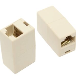 FEDUS 50 PCS RJ45 Cat5e Straight Network Cable Ethernet LAN Coupler Joiner Female to Female Connector Size:Pack of 50
  Bluetooth Speake (1 Pc) 13986
Reviews
There are no reviews yet.